
High Voltage Substation (HV Substation)
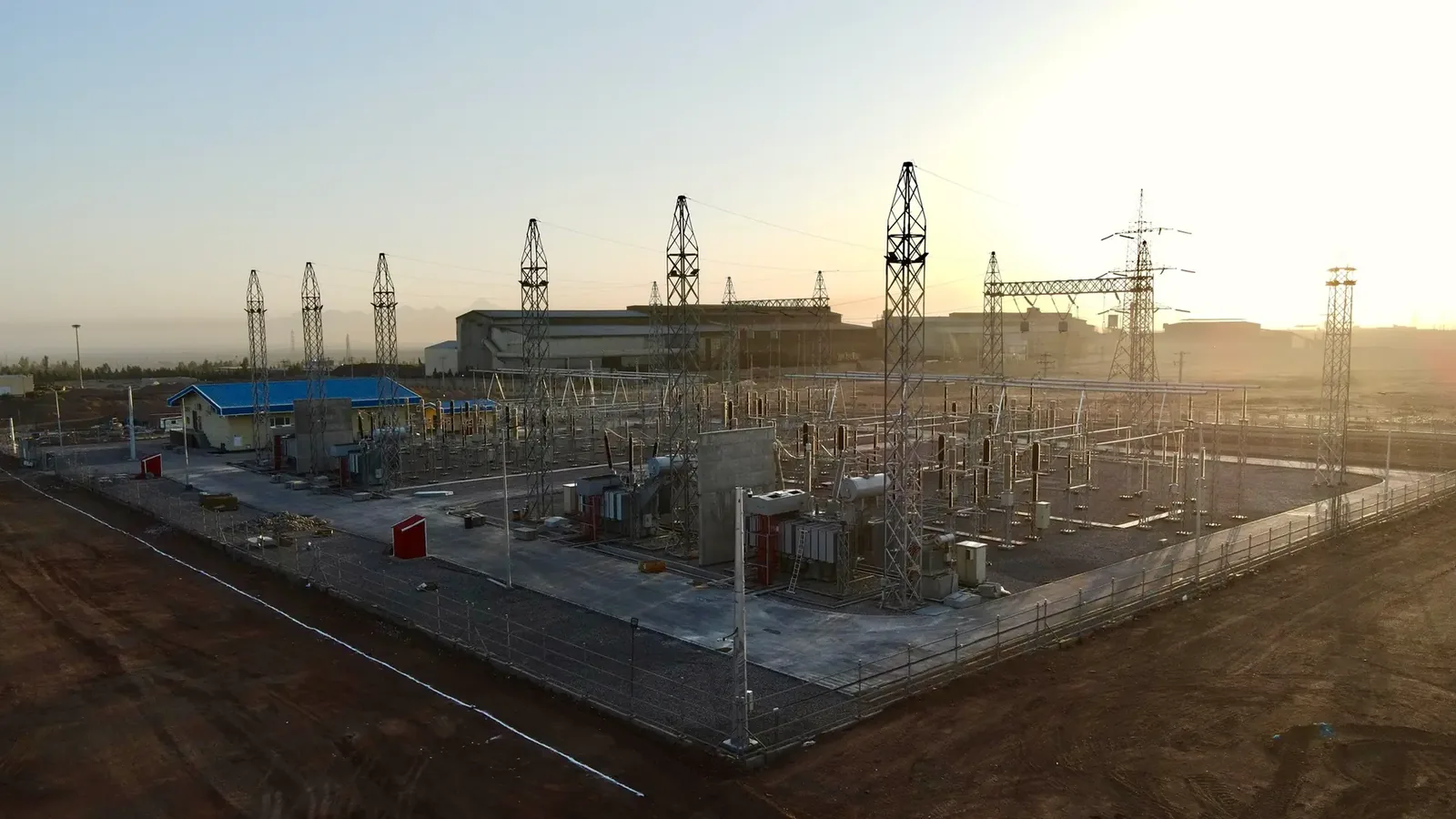
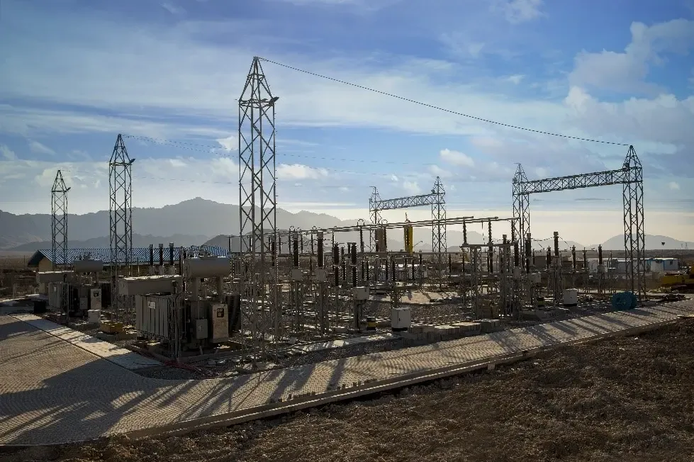
High Voltage Substations play a critical role as the connection point between solar power plants, Battery Energy Storage Systems (BESS/ESS) and the national grid. They ensure reliable power transmission, voltage transformation, protection and control of the system.
Advantages
- Stable transmission of generated power to the national grid
- Voltage transformation from MV up to HV levels of 400 kV
- Comprehensive protection against short-circuits, overloads and voltage fluctuations
- Capability to integrate renewable energy sources and energy storage systems
- Expandability for future capacity upgrades
Applications
- Utility-scale solar and wind power plants
- Large industrial and commercial complexes with high energy demand
- Microgrid and BESS integration with the national grid
- Regional and national transmission & distribution projects
Key Features
- High-efficiency power transformers
- Modern circuit breakers and disconnectors with automation capability
- Advanced and intelligent protection relays
- SCADA monitoring and control systems for precise operation and maintenance
- Robust design for diverse environmental and climatic conditions
- Seamless integration with PV and BESS for grid stability
- AIS (Air Insulated Substation): cost-effective, suitable for open outdoor spaces
- GIS (Gas Insulated Substation): compact, safe, ideal for limited-space or sensitive environments
Have a site that needs this?
Call the Powerst team or send your project scope — we'll get back with next steps.
Follow the power through the bay.
Hover or tap any component to see what it does. This is the path electricity takes through a single-busbar substation — from the incoming line, through the protection chain, across the busbar, to the transformer and out.
Gantry & Incoming Line
The steel portal that terminates the incoming transmission line and carries it into the bay. Power arrives here at full network voltage — 400, 230 or 63 kV.
Line Disconnector
The first isolating switch. It provides a visible break to isolate the bay from the incoming line for maintenance — operated off-load, only after the breaker has opened.
SF6 Circuit Breaker
The protective heart of the bay. It interrupts fault current in milliseconds, quenching the arc in SF6 gas. When protection detects a fault, this is what trips.
Current Transformer
Sits right after the breaker, scaling the primary current down to a safe signal for the protection relays and metering. Every protection decision starts here.
Busbar
The common conductor the whole substation shares — the spine. Once current passes the protection chain, it reaches the busbar and can be routed to any outgoing bay.
Bus Disconnector
Isolates the transformer bay from the busbar, so the transformer can be worked on while the rest of the substation stays live.
Power Transformer
Steps the voltage up or down between networks — the reason the substation exists. Oil-filled, with radiator fins and fans (ONAN/ONAF) carrying away the heat.
Outgoing Feeder
Power leaves at the new voltage level, heading to the next substation, an industrial load, or the distribution network.
Trace the current.
Hover any component in the diagram — or tap the chips below — to see its role in the power chain.
Gantry to
transformer.
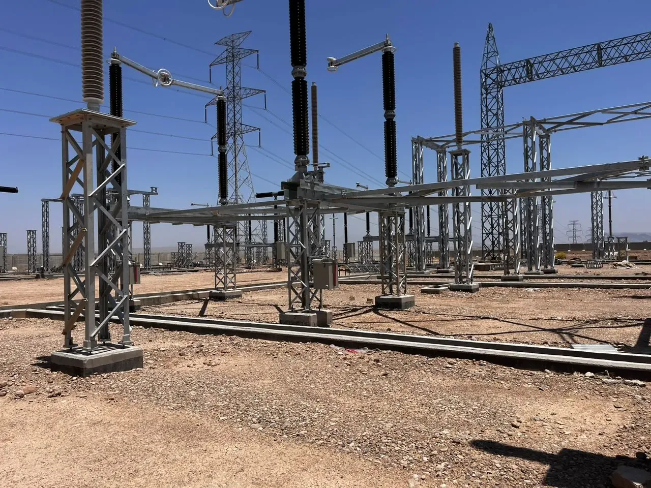
Every 400kV switchyard Powerst delivers is built as a coordinated system — portal gantries carrying the busbar, a switchgear row of breakers and instrument transformers, oil-immersed power transformers, and a control building running protection and SCADA.
- 01 Gantry & busbar structure
- 02 Switchgear row — breakers, disconnectors, CTs
- 03 Power transformers — ONAN / ONAF cooled
- 04 Control building & yard