
Transmission Lines
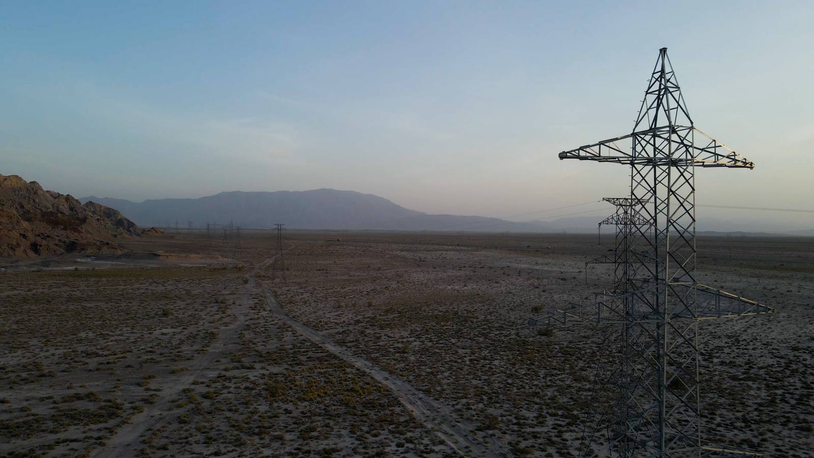
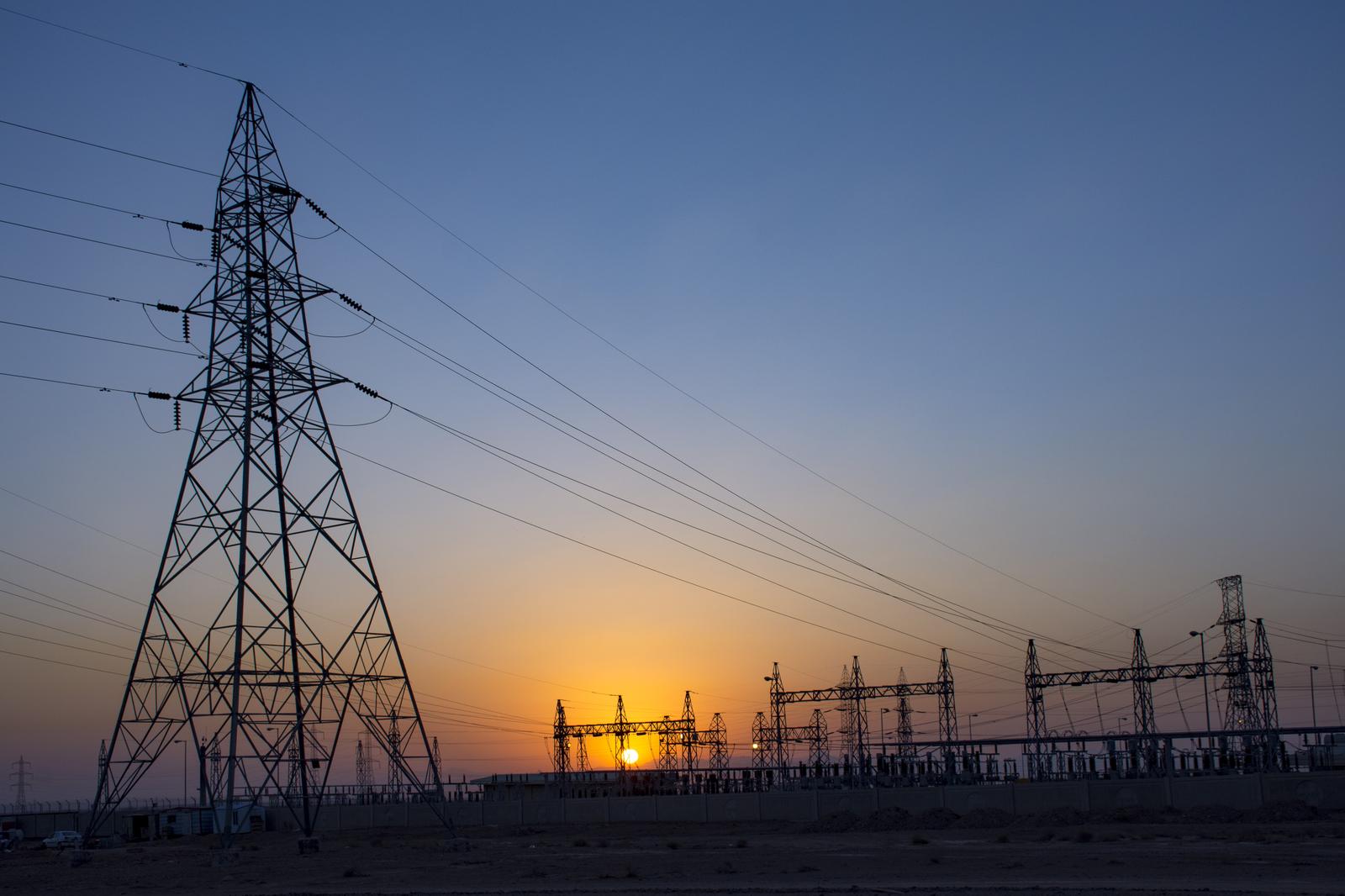
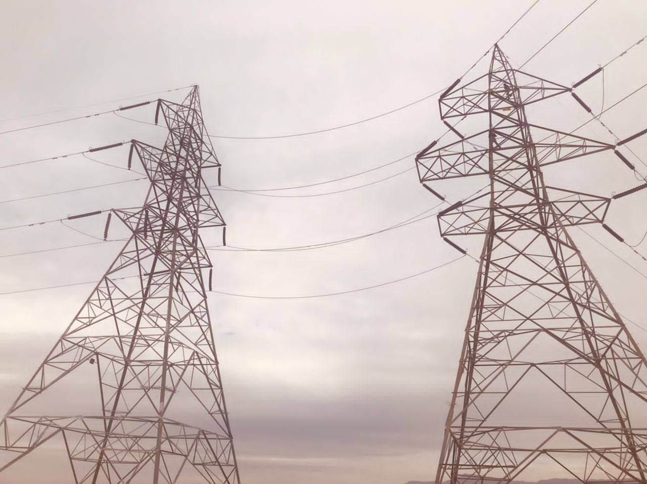
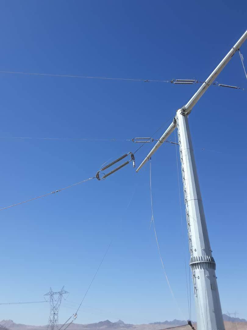
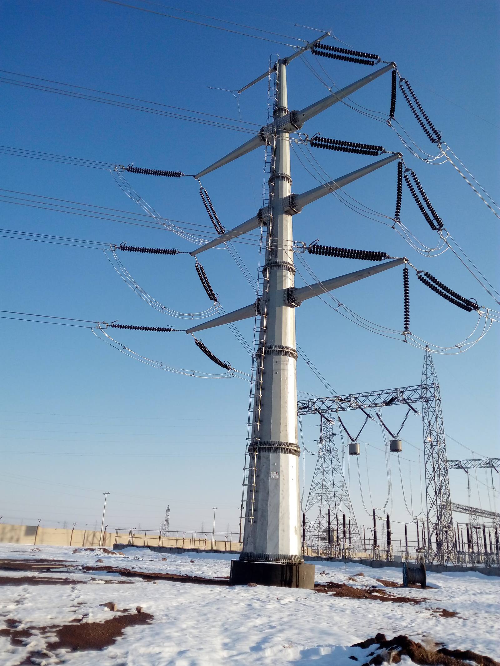
Transmission lines are a vital component of the power system, enabling the reliable transfer of electricity from renewable energy plants (such as solar and wind farms) to the national grid and end users. They ensure efficient, safe and long-distance power delivery, while maintaining grid stability and minimizing losses.
Advantages
- Reliable transfer of large-scale renewable energy to the grid
- Voltage levels up to 400 kV for long-distance transmission
- Reduced transmission losses with optimized conductor design
- Support for grid stability and integration of variable renewable sources
- Expandability to meet future power demand growth
Applications
- Connection of utility-scale solar and wind farms to the grid
- Regional and inter-regional power transmission
- Industrial complexes and large infrastructure projects
- Hybrid projects combining PV, BESS and substations
- Electrification of remote areas through high-voltage lines
Key Features
- Overhead Transmission Lines (OHTL): cost-effective, suitable for long distances and open terrain
- Underground Transmission Cables: compact, safe and ideal for urban or sensitive environments
- High-performance conductors with low-loss characteristics
- Modern insulation and protection technologies
- Advanced monitoring systems (thermal, fault detection, SCADA integration)
- Compliance with IEC, IEEE and local grid codes
- Robust design against environmental factors (wind, ice, seismic activity)
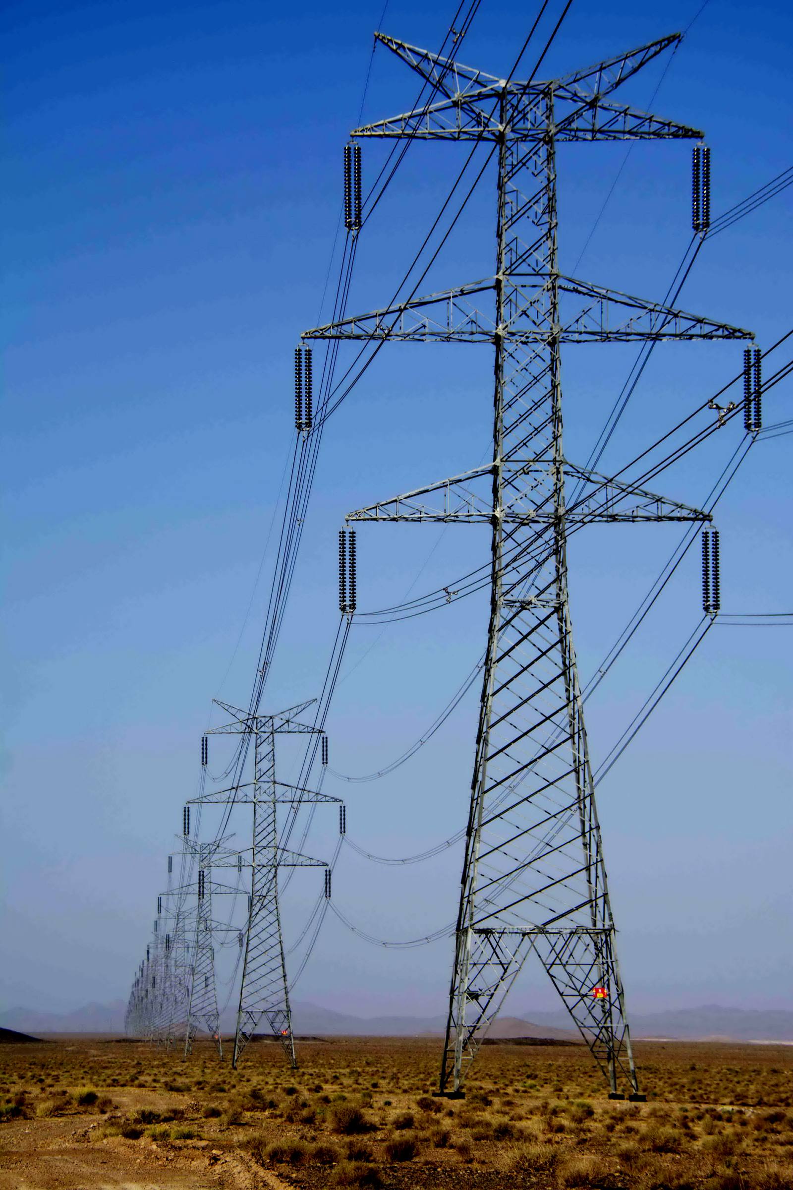
- In-house manufacturing of High Voltage Transmission Towers
Voltage & Capacity Range
Have a site that needs this?
Call the Powerst team or send your project scope — we'll get back with next steps.
Anatomy of a transmission span.
Hover or tap any part to see what it does. From the shield wire at the peak to the foundations below ground, this is what carries power across every kilometre of line Powerst builds.
Shield Wire / OPGW
The topmost wire, grounded to intercept lightning before it reaches the live conductors. On modern lines it's OPGW — carrying fiber-optic communication inside the same cable.
Cross-Arms
The horizontal members that hold the phase conductors out and apart, maintaining safe clearance from the grounded tower body and between phases.
Insulator Strings
Chains of disc insulators that suspend the energized conductor from the grounded cross-arm. More discs for higher voltage — that's how you read a line's class from the ground.
Bundled Conductors
The wires that carry the power. At high voltage they're bundled — two or more per phase — to cut corona loss and raise capacity.
Lattice Tower
The steel structure carrying it all. A suspension tower like this holds the conductors on vertical insulator strings along a straight run of the line.
Foundation
Reinforced concrete footings anchoring each leg against the tower's weight, wind and conductor tension — engineered for the soil at each location.
The Span & Sag
The distance to the next tower — typically 350–450 m at 400 kV. The conductor's sag between towers is engineered for both ground clearance and mechanical tension.
From sky to ground.
Hover any part of the tower and span — or tap the chips below — to see how a transmission line is built and what each element does.
Every bolt,
built for 400kV.
From the shield wire peak to the reinforced foundation, every Powerst transmission tower is sourced, inspected and erected to withstand extreme wind, ice and fault-current loads — supplied through a network of certified steel fabricators worldwide.
- 01 Shield wire & peak finial
- 02 Phase cross-arms — 400kV disc insulator strings
- 03 Lattice steel body — hot-dip galvanized
- 04 Leg extensions & reinforced foundation